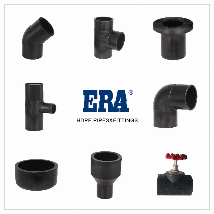
1.Extended Service Life
HDPE pipe is a safe and durable product ideal for your piping infrastructure. The service life of HDPE is estimated to be between 50 to 100 years, depending on application, design and installation.
2.Trenchless Installation
Traditional piping systems are installed by open cut (digging a ditch), resulting in traffic and environmental disruption. HDPE can be installed using this traditional open-cut method or by utilizing eco-friendly trenchless technology.
For trenchless installation, a horizontal directional machine bores a continuous hole beneath the ground. When the drilling head reaches the end of the bore, the pipe is attached and pulled back through the hole.
The flexibility of HDPE, combined with its outstanding tensile strength and abrasion resistance, make it the preferred and proven choice for trenchless installation technology
Detailed explanation of the core points of polyethylene pipeline connection construction
The connection quality of polyethylene pipes is the lifeline of the entire pipeline system. In engineering practice, its connection mainly adopts welding methods such as hot melt butt joint, electric melt connection, hot melt saddle connection, and hot melt socket connection. To ensure the reliability and long-term stability of the welding interface, the following are the core operational requirements that must be strictly followed.
1. Welding environment: the first line of defense for building quality
The welding environment has a decisive impact on the thermoplastic process.
Windproof and rainproof: Excessive wind speed or rainwater can directly carry away heat from the welding area, causing a sudden drop in the temperature of the heating plate and preventing the pipe end from reaching the ideal viscous state, resulting in"cold welding"or"false welding". Therefore, it is necessary to build windproof and rainproof shelters to create a stable"microclimate"for welding.
Low temperature protection: When the ambient temperature is below -5 ℃, the pipe itself becomes brittle and hard, and heat dissipation is extremely fast. At this point, in addition to necessary shed protection, preheating treatment should also be carried out on the area where the pipe is to be welded, and an infrared thermometer should be used to monitor the temperature at the pipe end to ensure that it reaches the minimum starting temperature specified in the welding process card before welding can proceed.
High temperature considerations: During the hot summer season, direct sunlight can cause the surface temperature of the pipe to be extremely high, possibly exceeding the lower limit of welding temperature. At this time, direct welding should be avoided at the highest temperature of the pipe body, and shading measures should be taken if necessary.
2. Welding surface cleanliness: the foundation for achieving perfect fusion
Any microscopic pollution will form defects at the fusion interface.
Cleaning standard: The welding surface and all tools in contact with it (such as heating plates and milling cutters) must achieve"surgical grade"cleanliness. Pollutants such as oil, soil, and moisture can hinder the mutual diffusion and entanglement of polyethylene molecular chains, significantly reducing welding strength.
Damage inspection: The end face of the pipe to be welded must not have any damage. Scratches that are too deep or caused by port collisions can become stress concentration points, affecting short-term strength and long-term fatigue resistance.
Operating standards: High purity alcohol (concentration ≥ 99.7%) and clean specialized cotton cloth should be used for cleaning, and the use of any organic solvents (such as acetone and gasoline) is strictly prohibited. After cleaning, it is strictly prohibited to touch the processed port with hands or dirty gloves.
3. Welding limitations for small-diameter/thin-walled pipelines: preferred electric fusion connection
For pipeline components with a nominal outer diameter dn ≤ 63mm or a nominal wall thickness en<6mm, it is mandatory to use electric fusion connections for the following reasons:
Limitations of hot melt bonding:
Difficulty in clamping and alignment: The smaller the pipe diameter and the thinner the wall thickness, the poorer its stability in the fixture. A slight lack of roundness or misalignment can lead to a significant reduction in the contact area of the welding end face, resulting in ineffective welding.
Impact of weld bead (flanging): Hot melt docking will form a circle of weld bead on the inner wall of the pipeline. For small-diameter pipelines, this weld can significantly increase fluid resistance and may even cause blockage.
Advantages of electric fusion connection: Electric fusion fittings are uniformly heated internally through resistance wires, and fusion is achieved through expansion pressure. The roundness and clamping alignment requirements of the pipe are relatively low, which can effectively ensure the welding quality of small-diameter pipelines, and the inner wall is smooth without flow obstruction.
4. Welding of dissimilar materials: Avoiding compatibility risks
When it is necessary to connect polyethylene pipes of different material grades (such as PE80 and PE100), electric fusion connection must be used.
Root cause: There are differences in the base resin, molecular weight, and distribution between PE80 and PE100, resulting in different melt mass flow rates (MFR). The difference in MFR means that their flowability and viscoelasticity are not consistent under the same heating conditions. If hot melt docking is used, the molecular chains of the two materials cannot fully penetrate and entangle with each other, and the weld joint will become a weak link in the entire system.
The solution of electric melting: The electric melting connection melts the outer and inner walls of the pipe and the pipe through the heating wire inside the pipe, and completes the fusion through constant expansion pressure in a closed confined space, which can better overcome material compatibility issues and achieve reliable molecular chain entanglement.
5. Welding of pipes with different wall thicknesses/SDR values: achieving equal strength transition
When welding pipeline components of different SDR series (i.e. with different wall thicknesses), it is recommended to follow the following principles:
Preferred electric fusion connection: The design of electric fusion fittings has taken into account the difference in wall thickness, and can achieve uniform stress transition through internal structural design, which is the simplest and most reliable method.
Detailed explanation of the core points of polyethylene pipeline connection construction
The connection quality of polyethylene pipes is the lifeline of the entire pipeline system. In engineering practice, its connection mainly adopts welding methods such as hot melt butt joint, electric melt connection, hot melt saddle connection, and hot melt socket connection. To ensure the reliability and long-term stability of the welding interface, the following are the core operational requirements that must be strictly followed.
1. Welding environment: the first line of defense for building quality
The welding environment has a decisive impact on the thermoplastic process.
Windproof and rainproof: Excessive wind speed or rainwater can directly carry away heat from the welding area, causing a sudden drop in the temperature of the heating plate and preventing the pipe end from reaching the ideal viscous state, resulting in"cold welding"or"false welding". Therefore, it is necessary to build windproof and rainproof shelters to create a stable"microclimate"for welding.
Low temperature protection: When the ambient temperature is below -5 ℃, the pipe itself becomes brittle and hard, and heat dissipation is extremely fast. At this point, in addition to necessary shed protection, preheating treatment should also be carried out on the area where the pipe is to be welded, and an infrared thermometer should be used to monitor the temperature at the pipe end to ensure that it reaches the minimum starting temperature specified in the welding process card before welding can proceed.
High temperature considerations: During the hot summer season, direct sunlight can cause the surface temperature of the pipe to be extremely high, possibly exceeding the lower limit of welding temperature. At this time, direct welding should be avoided at the highest temperature of the pipe body, and shading measures should be taken if necessary.
2. Welding surface cleanliness: the foundation for achieving perfect fusion
Any microscopic pollution will form defects at the fusion interface.
Cleaning standard: The welding surface and all tools in contact with it (such as heating plates and milling cutters) must achieve"surgical grade"cleanliness. Pollutants such as oil, soil, and moisture can hinder the mutual diffusion and entanglement of polyethylene molecular chains, significantly reducing welding strength.
Damage inspection: The end face of the pipe to be welded must not have any damage. Scratches that are too deep or caused by port collisions can become stress concentration points, affecting short-term strength and long-term fatigue resistance.
Operating standards: High purity alcohol (concentration ≥ 99.7%) and clean specialized cotton cloth should be used for cleaning, and the use of any organic solvents (such as acetone and gasoline) is strictly prohibited. After cleaning, it is strictly prohibited to touch the processed port with hands or dirty gloves.
3. Welding limitations for small-diameter/thin-walled pipelines: preferred electric fusion connection
For pipeline components with a nominal outer diameter dn ≤ 63mm or a nominal wall thickness en<6mm, it is mandatory to use electric fusion connections for the following reasons:
Limitations of hot melt bonding:
Difficulty in clamping and alignment: The smaller the pipe diameter and the thinner the wall thickness, the poorer its stability in the fixture. A slight lack of roundness or misalignment can lead to a significant reduction in the contact area of the welding end face, resulting in ineffective welding.
Impact of weld bead (flanging): Hot melt docking will form a circle of weld bead on the inner wall of the pipeline. For small-diameter pipelines, this weld can significantly increase fluid resistance and may even cause blockage.
Advantages of electric fusion connection: Electric fusion fittings are uniformly heated internally through resistance wires, and fusion is achieved through expansion pressure. The roundness and clamping alignment requirements of the pipe are relatively low, which can effectively ensure the welding quality of small-diameter pipelines, and the inner wall is smooth without flow obstruction.
4. Welding of dissimilar materials: Avoiding compatibility risks
When it is necessary to connect polyethylene pipes of different material grades (such as PE80 and PE100), electric fusion connection must be used.
Root cause: There are differences in the base resin, molecular weight, and distribution between PE80 and PE100, resulting in different melt mass flow rates (MFR). The difference in MFR means that their flowability and viscoelasticity are not consistent under the same heating conditions. If hot melt docking is used, the molecular chains of the two materials cannot fully penetrate and entangle with each other, and the weld joint will become a weak link in the entire system.
The solution of electric melting: The electric melting connection melts the outer and inner walls of the pipe and the pipe through the heating wire inside the pipe, and completes the fusion through constant expansion pressure in a closed confined space, which can better overcome material compatibility issues and achieve reliable molecular chain entanglement.
5. Welding of pipes with different wall thicknesses/SDR values: achieving equal strength transition
When welding pipeline components of different SDR series (i.e. with different wall thicknesses), it is recommended to follow the following principles:
Preferred electric fusion connection: The design of electric fusion fittings has taken into account the difference in wall thickness, and can achieve uniform stress transition through internal structural design, which is the simplest and most reliable method.
The premise of hot melt docking: If hot melt docking must be used, the wall thickness of the thicker pipe end must be machined (such as milling with a lathe) to be consistent with the wall thickness of the thinner pipe end, forming an"equal thickness docking surface". Directly connecting without this treatment may result in warping and deformation of the weld due to differences in cooling shrinkage rate and internal stress, leaving serious hidden dangers.
6. Adequate cooling: a key process for eliminating internal stress
After welding is completed, the joint must undergo sufficient natural cooling without disturbance or external force.
Principle: The welding process forms a new crystalline structure at the joint. If moved, rotated, or subjected to external forces before cooling and solidification, it will disrupt the rearrangement and crystallization process of molecular chains, resulting in freezing stress inside and greatly reducing the long-term strength and service life of the weld.
Operation requirements: The cooling time specified in the process card must be strictly followed. It is strictly prohibited to use any means such as splashing water or blowing air to forcibly cool down. During the cooling period, the welding fixture must not be loosened until the temperature drops to ambient temperature.
7. On site static placement: a necessary step to eliminate temperature difference stress
When there is a significant temperature difference between the storage site and the construction site (usually>10 ℃), the pipes and fittings must be placed in a shaded area at the construction site for at least 24 hours before connection.
Purpose: To make its temperature slowly and uniformly approach the ambient temperature of the construction site.
Importance: Temperature difference can cause thermal expansion and contraction of pipe size. If static balancing is not carried out, the interface with qualified dimensions during welding may experience significant tensile stress due to shrinkage or compressive stress during expansion after temperature balancing, which may lead to interface failure under long-term operation.
The connection of polyethylene pipes is a rigorous science. From environmental control to material compatibility treatment, every step is based on the principles of polymer materials science. Only by deeply understanding the"why"behind each requirement and implementing it meticulously during construction can a truly safe, durable, and leak free pipeline system be created.
Detailed Explanation of Technical Regulations for Pipeline Hydraulic Test
The hydrostatic test is the final and most critical step in inspecting the construction quality of the water supply pipeline system. Its purpose is to evaluate the strength, tightness, and interface quality of the pipeline, ensuring long-term safety after the system is put into operation.
I. General Provisions
It is strictly prohibited to use air pressure instead of water pressure test
Root cause: Water is an incompressible fluid, while gas is compressible. Once the pipeline ruptures during the testing process, the enormous energy accumulated in the compressed gas will be instantly released, causing a violent explosion that destroys the pipeline and generates high-speed splashing fragments, posing extreme danger to personnel and equipment. Hydrostatic testing is much safer, as even if the pipeline fails, it will only result in leakage rather than explosion.
Regulation: Water supply pipeline systems, regardless of diameter and pressure, must undergo hydrostatic testing.
Water immersion and preliminary inspection
Soaking purpose:
Fully saturate the pipeline: eliminate any air that may be adsorbed on the inner wall of the pipeline to ensure stable pressure during testing.
Temperature balance: To achieve a basic balance between the pipe, backfill soil, and water temperature, avoiding pressure fluctuations caused by temperature differences that may affect the judgment of the results.
Initial stability: Allow the newly installed pipeline to complete initial stress release and settlement in a water carrying state.
Operation requirement: The soaking time should not be less than 12 hours. For pipe sections with larger diameters (DN ≥ 600) or complex geological conditions, it is recommended to extend the soaking time appropriately. During the water filling process, all high point exhaust valves should be opened and closed upon seeing water.
External dew point inspection: After filling with water and before backfilling, a thorough inspection must be carried out on all exposed connection points such as unfilled interfaces, flanges, valve well wall penetrations, etc. Any leakage found must be immediately marked and treated. This step can eliminate most obvious defects in advance.
Experimental segmentation principle
Length control:
General pipe section: should not exceed 1000 meters. If it is too long, the volume will be huge, making it more difficult to apply pressure, replenish water, and determine leakage points.
Equipped with accessory pipe sections: For pipe sections installed with valves, tees, fire hydrants, and other accessories, the length should not exceed 500 meters. These components are potential weak points that require more detailed inspection.
Material differentiation: If there are connections made of different materials (such as PE pipes and steel pipes, ductile iron pipes) in the system, they must be pressure tested separately. Due to the different elastic moduli, pressure bearing capacities, and testing standards of different materials, mixed pressure testing cannot accurately evaluate the quality of each interface and the overall reliability of the system.
2、 Preparation for pressure test
The thoroughness of the preparation work for pressure testing is a prerequisite for the success of the experiment.
Design of pressure testing engineering
Pressure testing is not simply about applying pressure. A special plan should be prepared in advance, which should include:
Back design: Calculate the thrust on the pipe end blocking plate (blind plate), design reliable support structures (such as backrest walls and support piles), and prevent pipe fittings from flying out during pressure testing.
Pipeline design: Clearly define the connection positions and diameters of the inlet pipe, booster pump, pressure gauge, exhaust valve, and drainage diversion pipe to ensure smooth inlet, thorough exhaust, and safe drainage.
Equipment selection: Based on the test pressure and pipe section volume, select a suitable booster pump and a pressure gauge with matching range and qualified accuracy.
Safety plan: Designate a pressure test warning area and develop emergency pressure relief and evacuation plans in case of sudden leaks or support failures.
End support inspection
Before pressure testing, a comprehensive inspection of the blocking plate and its supporting structure must be conducted to confirm the firmness of its welding, anchoring, and support.
It is strictly prohibited to use valves in the system as pressure test sealing plates. The pressure bearing direction and structural strength of the valve are not designed for this purpose, and forcibly using it as a sealing plate can easily lead to valve damage and serious accidents.
Pressure measuring device
Preferred pressurization equipment with digital display, capable of accurately controlling the pressurization process and measuring the amount of water replenishment.
If a spring pressure gauge is used, it must meet the following requirements:
The accuracy shall not be lower than level 1.5.
The range is 1.3 to 1.5 times the test pressure. A range that is too small can easily damage the instrument, while a range that is too large can reduce reading accuracy.
The diameter of the dial should not be less than 150mm, making it easy to observe remotely and reducing reading errors.
Isolation of pressure testing system
The pressure test pipe section should be a"pure"system, and all accessories that are not involved in the pressure test or are easily damaged must be isolated, such as water hammer eliminators, outdoor fire hydrants, safety valves, flow meters, etc.
All valves in the system should be fully open to ensure that the entire pipe section is subjected to pressure testing and avoid blind spots.
3、 Pressure testing process
The hydrostatic test should strictly follow the two-stage method of"pre test"and"main test"to scientifically distinguish the reasons for pressure drop.
(1) Pre experimental stage
The purpose of this stage is to expose and eliminate significant leaks and initial volume changes.
Pressure relief and stabilization: Reduce the water pressure inside the pipeline to atmospheric pressure and maintain it for 60 minutes. During this period, the inlet valve should be closed and the pressure should be observed to see if it rises. If it does, it indicates that there is still air in the system that has not been completely discharged and needs to be re discharged.
Boosting and preliminary inspection:
Slowly increase the pressure to the test pressure (Ps) and stabilize for 30 minutes.
During this period, it is allowed to maintain Ps by injecting water to supplement pressure, but overpressure is strictly prohibited.
Organize personnel to conduct a comprehensive inspection, focusing on checking for leaks and sweating in interfaces and accessories. Once discovered, immediately stop pressure testing, rectify after pressure relief, and start the testing process from scratch.
Stability observation of stop pressure:
Stop injecting water and pressure, stabilize for 60 minutes.
Qualification standard: After 60 minutes, the pressure drop shall not exceed 70% of the test pressure Ps. The pressure should be maintained at least above 0.3Ps.
If it is not qualified: it indicates that there is significant leakage or continuous volume change, and the cause must be identified by depressurization, treated, and restarted.
(2) Main experimental phase
This stage aims to determine the micro leakage and elastic deformation performance of the pipeline system through more precise observation.
Discharge volume test:
After passing the pre test, reduce the pipeline pressure by 10% to 15% of the test pressure (such as from Ps to 0.85Ps~0.9Ps).
Accurately measure the amount of water released during this depressurization process, △ V (liters).
Calculate the maximum allowable discharge capacity △ Vmax:
△Vmax = 1.2V △P {1/Ew + di/(enEp)}
Formula interpretation: This formula calculates the theoretical maximum allowable water output of a pipeline within the elastic deformation range due to pressure reduction. It consists of two parts: 1.2V △ P/Ew represents the compressive recovery of water, and 1.2V △ P di/(enEp) represents the elastic recovery of the pipe wall.
Result judgment: If the measured △ V>△ Vmax, it indicates that there is excessive water outflow and leakage, and the test is unqualified. It is necessary to release pressure, eliminate air and check for leaks, and then restart from the pre-test stage.
Observation of pressure change trend:
After passing the water discharge test, start recording the remaining pressure of the pipeline.
Qualification criterion one (optimal): Within 30 minutes, the pressure record shows an upward trend. This indicates that slight shrinkage of the pipeline or slight positive fluctuations in water temperature is a sign of excellent system tightness.
Qualification criterion two (allowed): If there is no upward trend in pressure within 30 minutes, the observation shall be extended to 90 minutes. If the total pressure drop within 90 minutes does not exceed 0.02 MPa, the test result is also qualified. This standard allows for minimal leakage and slow temperature loss.
Final judgment:
If one of the above two conditions is met, the hydrostatic test is qualified.
If none of them meet the requirements, it will be judged as unqualified. It is necessary to thoroughly investigate the reasons (such as hidden leaks, excessive temperature influence, incomplete air discharge, etc.), take corresponding measures, and then reorganize the pressure test.
summary
Hydrostatic testing is a rigorous and systematic process, with each step based on principles of fluid mechanics and materials science. Strictly implementing this regulation not only ensures the quality of the project, but also reflects the responsibility for project safety and social public safety.


 English